Language
GET A QUOTE

GET A QUOTE
Language
GET A QUOTE
GET A QUOTE


Bed Head Unit 230 Assembly: A Look Inside the Workshop
These workshop photographs follow the assembly of the Kersai Bed Head Unit 230, from the open housing and panel fittings to the gas terminal covers, electrical faceplates and end covers.
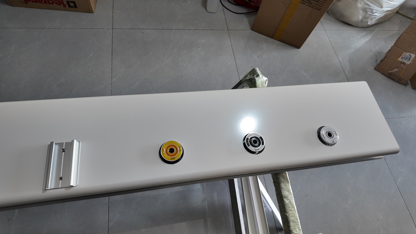
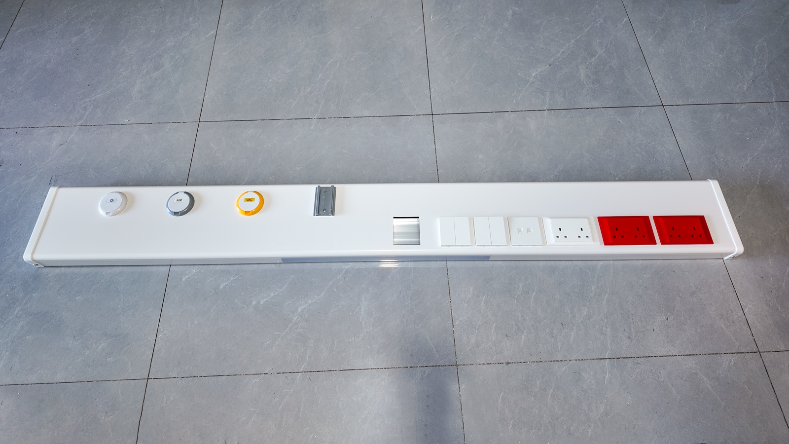
The units shown combine O₂, AIR and VAC terminals with red and white power sockets, switches, a short accessory rail and a reserved interface opening. The photographs show the configuration of this batch.
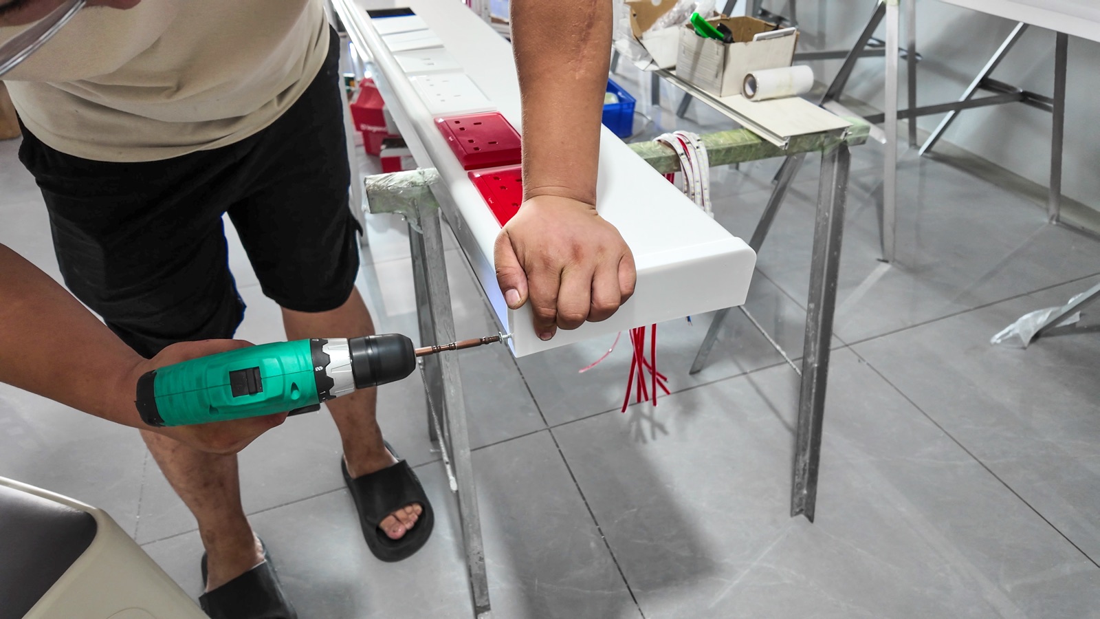
The front panel provides openings for the selected modules. The photographs below show the panel layout, its fit with the housing and the attachment of the short accessory rail.
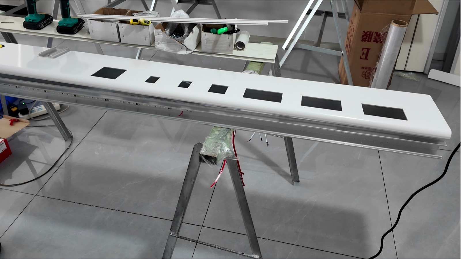
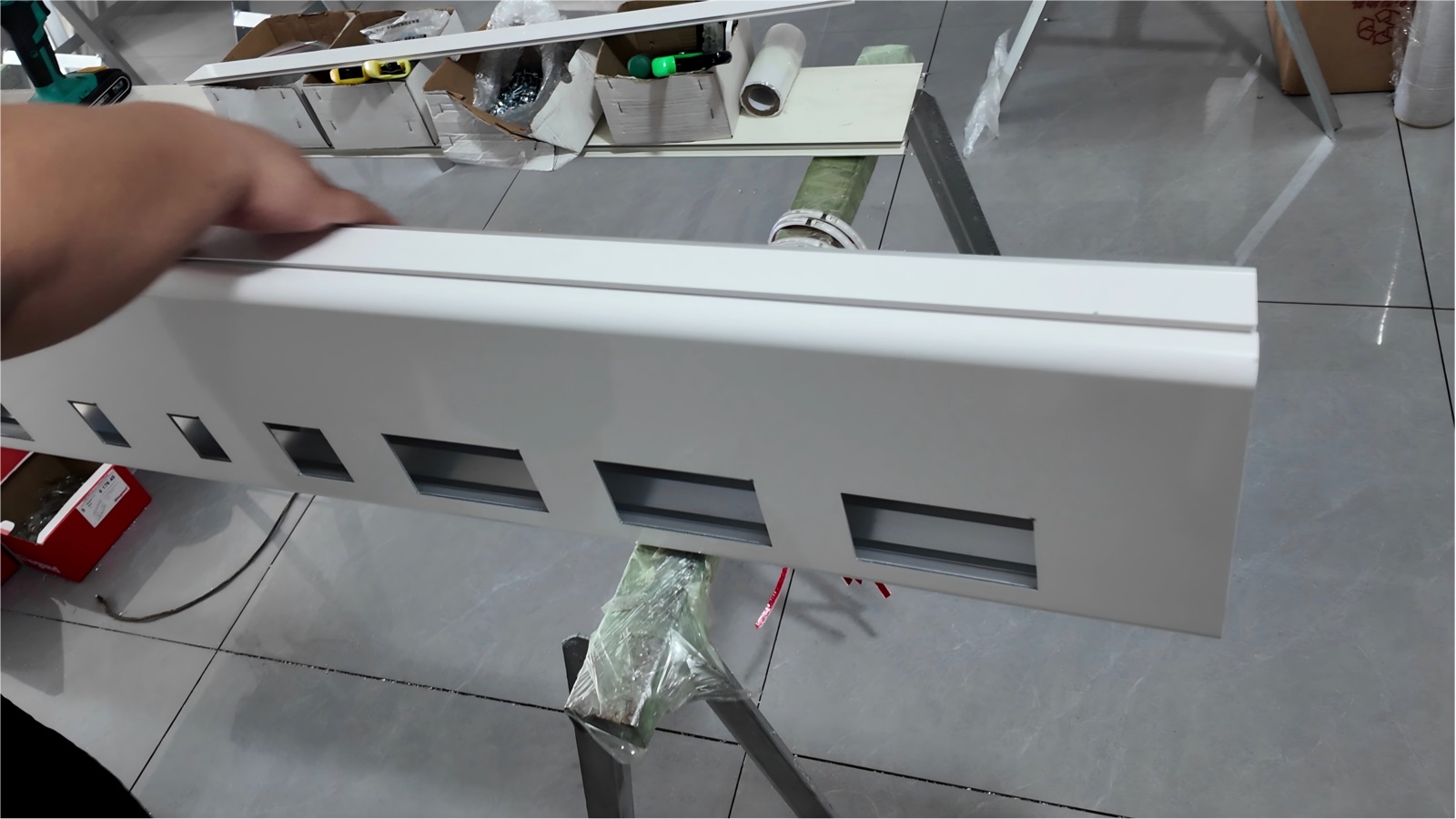
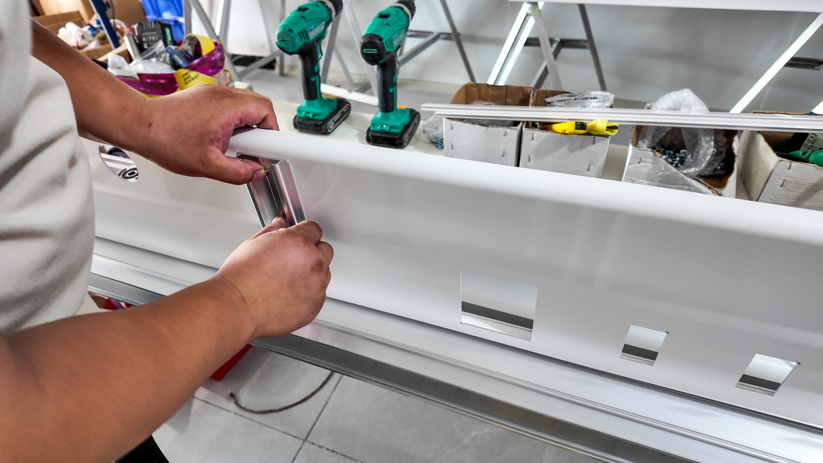
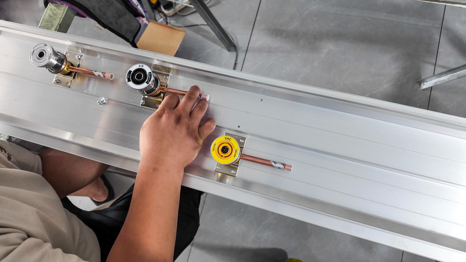
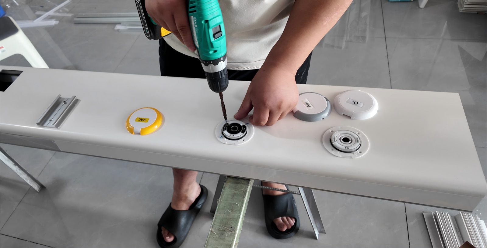
Inside the housing, the gas terminal assemblies include copper tube connections. The O₂, AIR and VAC markings identify the three services shown. Further assembly brings the terminals through the front panel and adds their surrounds and identification covers.
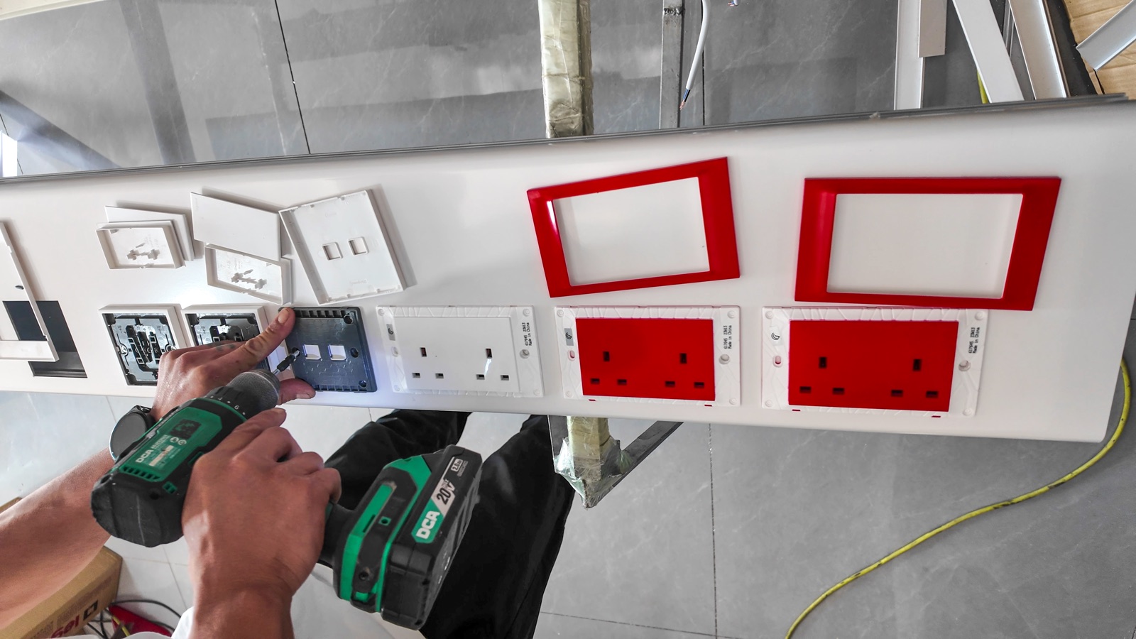
The electrical modules are fastened to the panel before the outer faceplates are fitted. These photographs show the red and white sockets alongside the other panel modules.
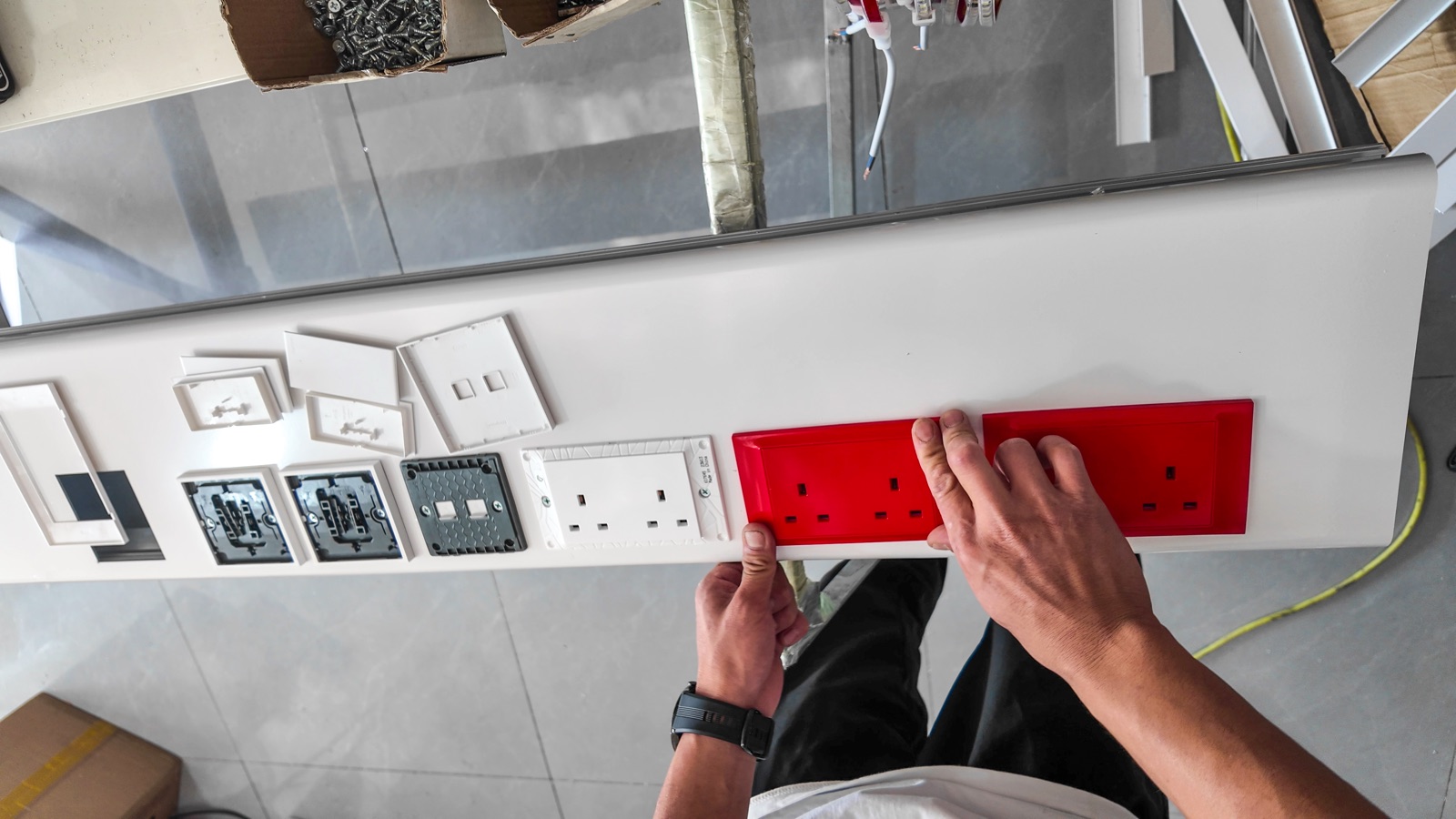
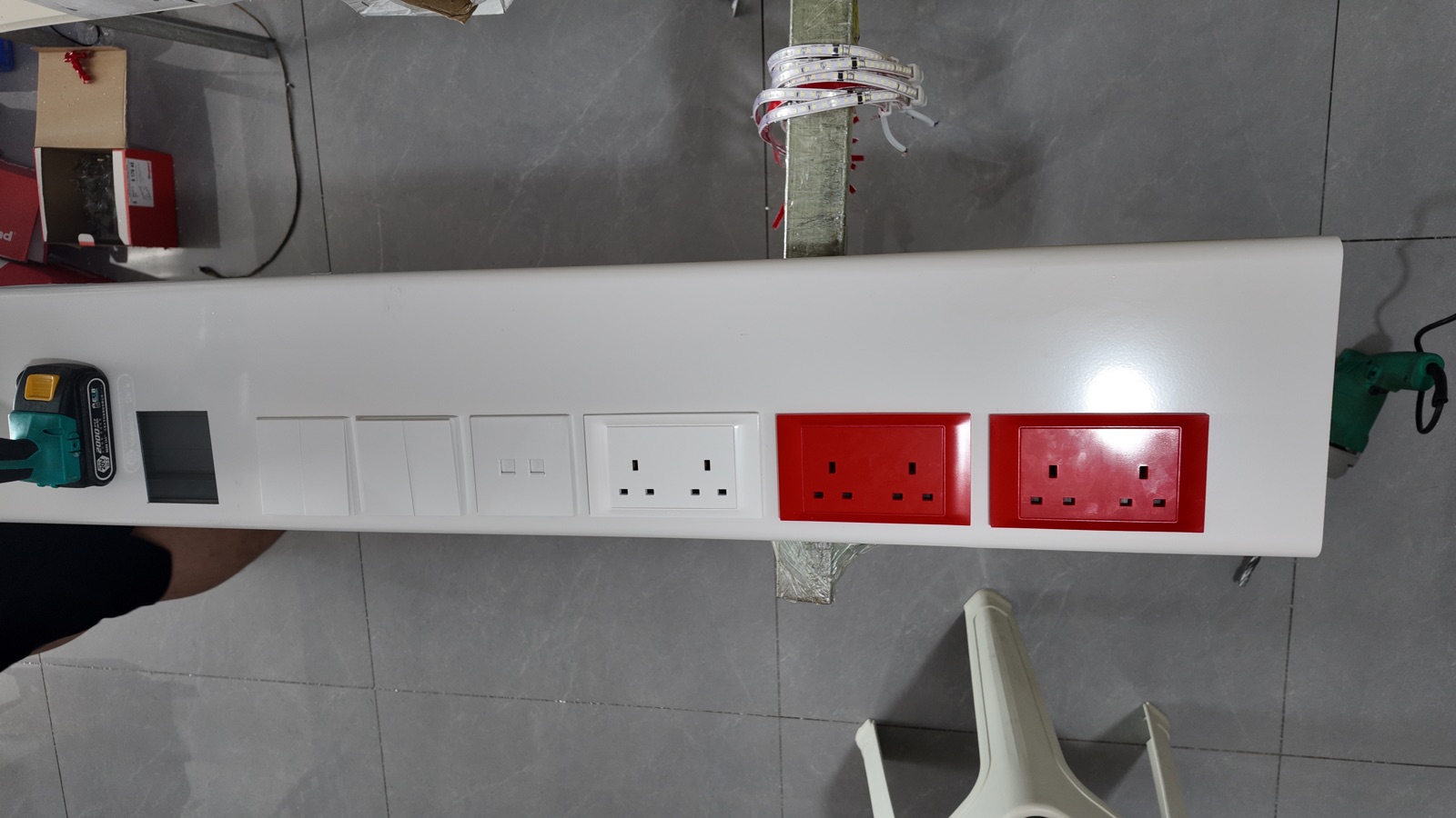
The end cover is secured to the housing. The overall view shows the arrangement of the gas terminals and electrical modules, together with the reserved interface opening.
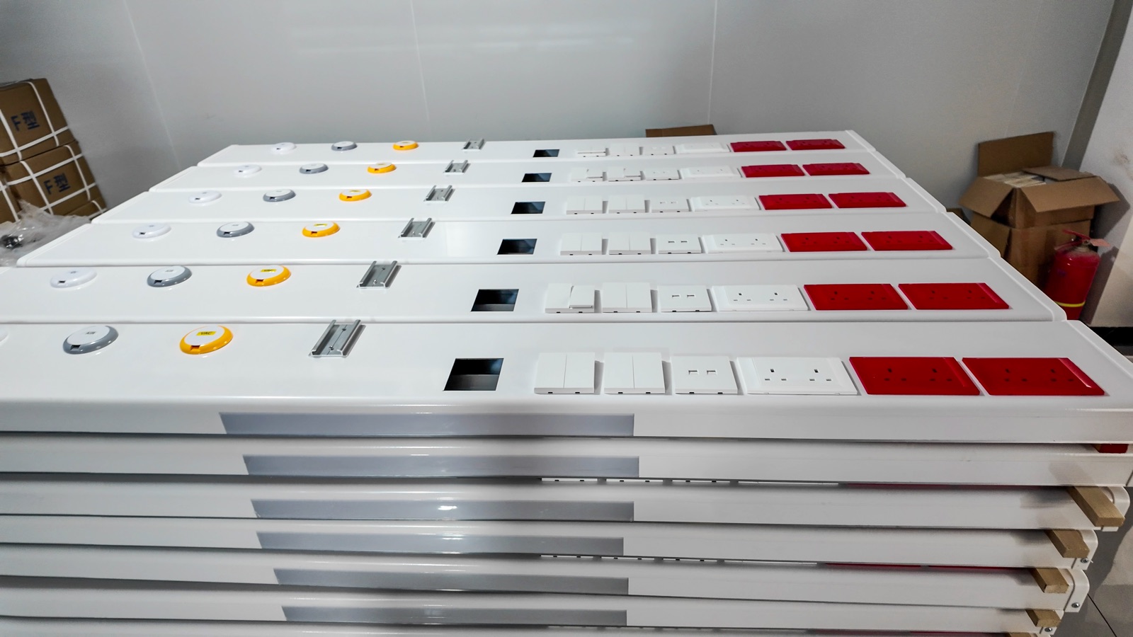
The final workshop view brings together multiple units with the same visible panel layout.
Product details: View the Bed Head Unit 230 specifications and product information.
Expand the gallery to browse all 12 photographs. Select a photograph to open the larger image.
INQUIRE IMMEDIATELY

We are a solutions-driven medical technology company committed to delivering reliable Medical Gas Pipeline System components, supporting healthcare infrastructure, and creating long-term value for global medical projects.
CONTACT US
Room 1401, 14th Floor, Unit 3, No. 467 Changjiang Middle Road, Huangdao, Qingdao,China
MENU
SUBSCRIBE TO OUR NEWSLETTER
If you are interested in our products, please subscribe to our email
©2026 QINGDAO KERSAI MEDICAL DEVICES CO.,LTD. ALL RIGHTS RESERVED. POWERED BY HICHENG


